
12-03-2019
New uses for plastic tubes are showing up under the hood. The changes are coming at a steady pace. Are you ready to respond to new demands coming from tier-one suppliers?
Read More >
25-02-2019
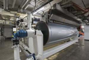
Part two of the chill roll series provides tips for care of rubber covered rolls as well as grinding and maintenance.
Read More >
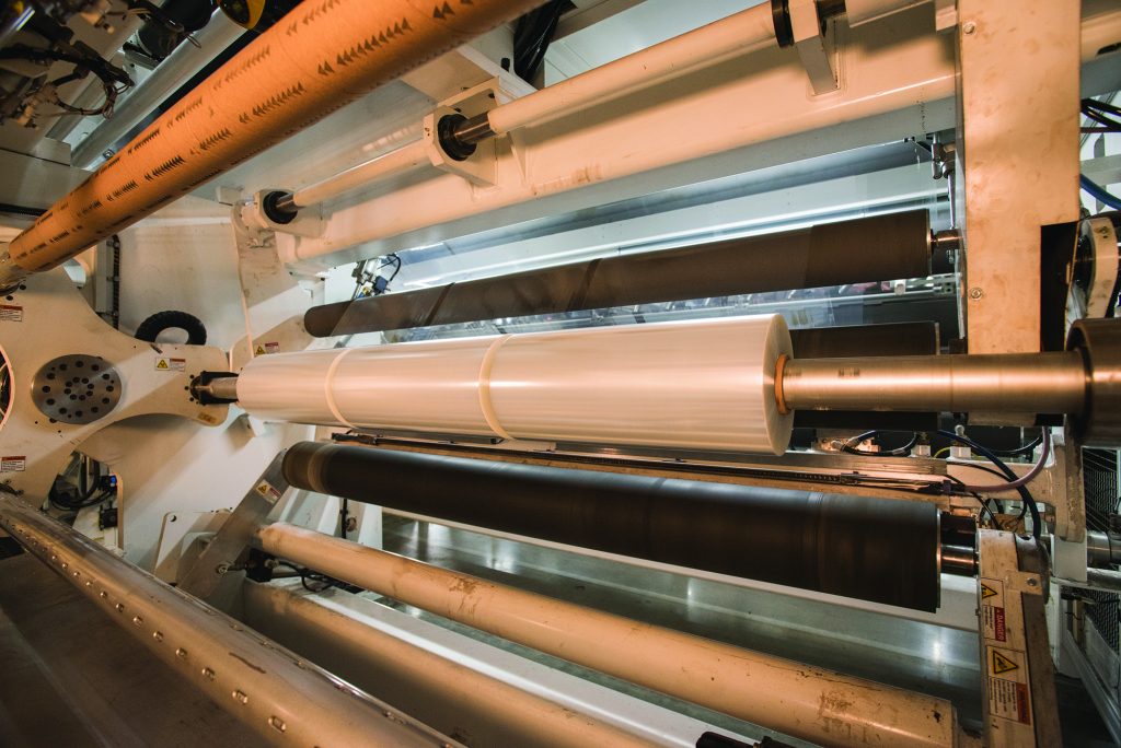
11-02-2019
Discover our tips and tricks for roll maintenance to maximizing cast film and extrusion coating equipment performance and longevity.
Read More >
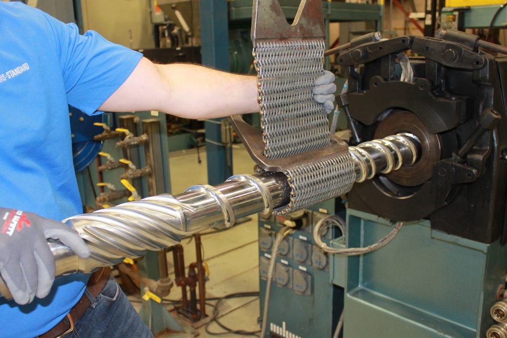
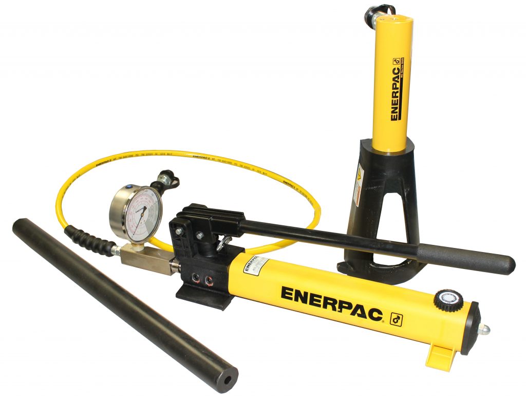
08-01-2019
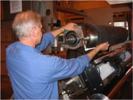
10-steps applicable to feedscrew removal for most Davis-Standard extruders using a feedscrew jack
Read More >
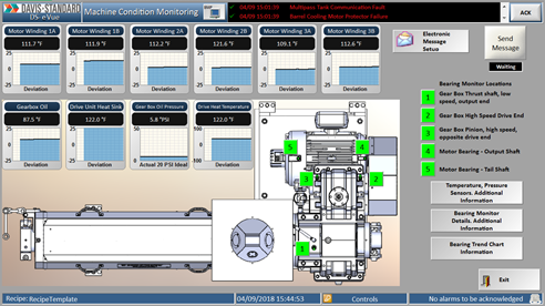
17-12-2018
Are you taking advantage of extrusion monitoring solutions and capabilities? SMART Technology helps to harness cost-savings while maintaining quality and competitiveness.
Read More >
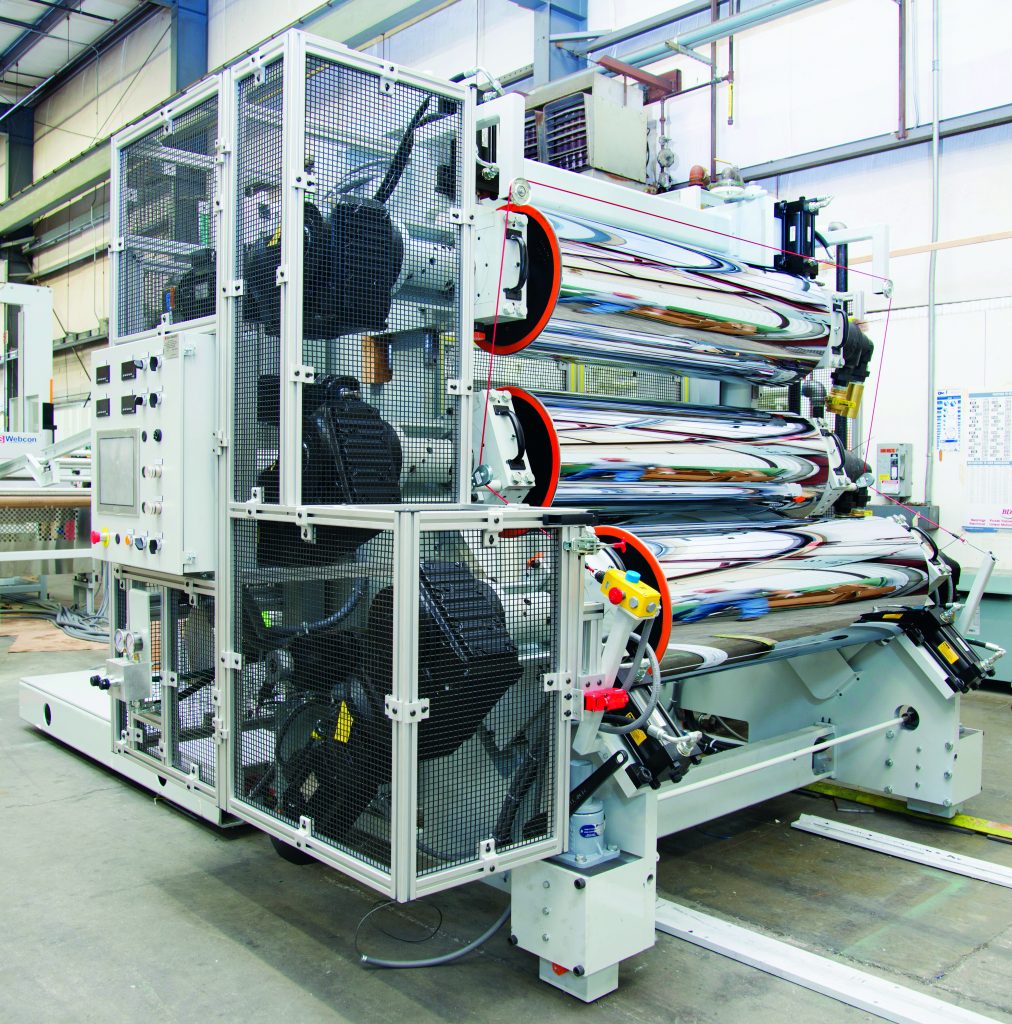
03-12-2018
When is the last time you checked the roll surfaces on your roll stand? Periodic roll maintenance is essential for optimal sheet processing and to get the most out of your investment.
Read More >
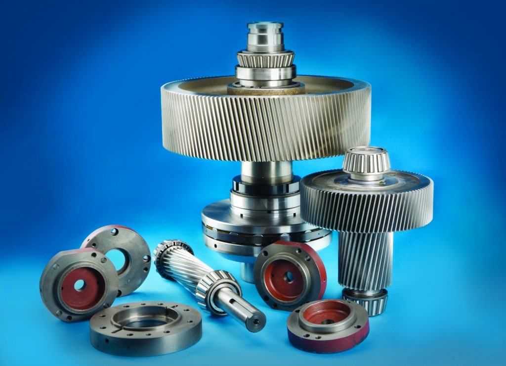
20-11-2018
Keeping the gearcase in prime condition can significantly impact your bottom line. Here are five tips to keep the engine of your extruder running strong.
Read More >
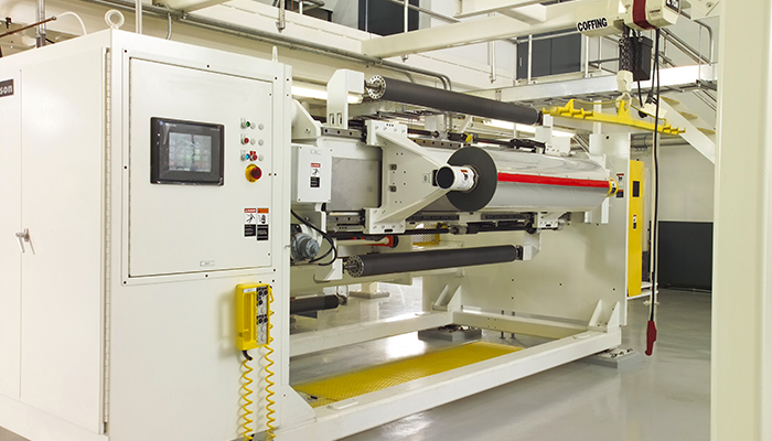
05-11-2018
Producing high-quality, shippable rolls directly off your film line presents an ideal situation. Here's how to take advantage of the pros!
Read More >
22-10-2018
There is no way to get around it. Every flexible film producer is faced with the challenge of producing quality film rolls with imperfect films.
Read More >