


12-08-2019
Our K fair veterans have compiled a list to help you survive the K fair marathon and get across the finish line in good shape.
Read More >
29-07-2019
We’ve called on the experience of our veteran teammates to help you navigate K2019 and get the most out of your experience. This first blog gets us started with 10 things to know as you prepare for this mammoth show.
Read More >
16-07-2019
A systematic shutdown and restart are essential to minimize purge time and ensure a smooth restart. Check out these procedures to minimize material degradation and waste.
Read More >
24-06-2019
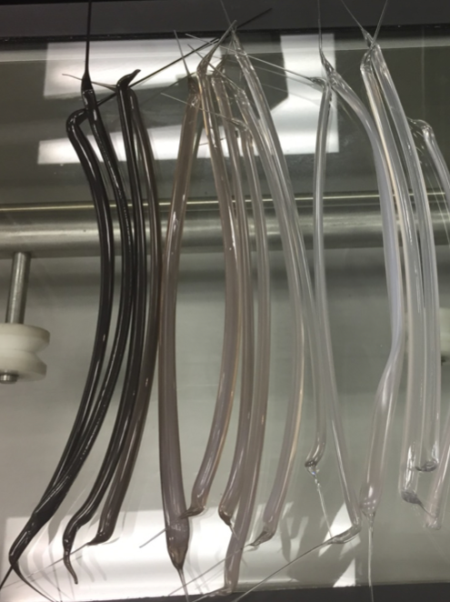
Incorrect purging procedures for product changeover, line shutdown and restart can lead to premature polymer degradation that will significantly impact yield and productivity, and lead to unwanted downtime. This blog post will cover common sense purging methods that can increase uptime and minimize waste.
Read More >
11-06-2019
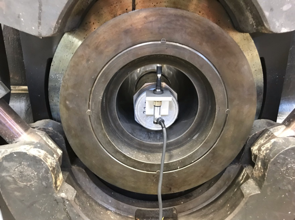
In the blog post, Essential Feedscrew and Barrel Maintenance Part I, we discussed the importance of maintaining the clearance between the screw and barrel on your extruder to ensure that your equipment is operating at maximum efficiency. This blog will examine how to accurately measure the inner diameter of the extruder barrel.
Read More >
28-05-2019
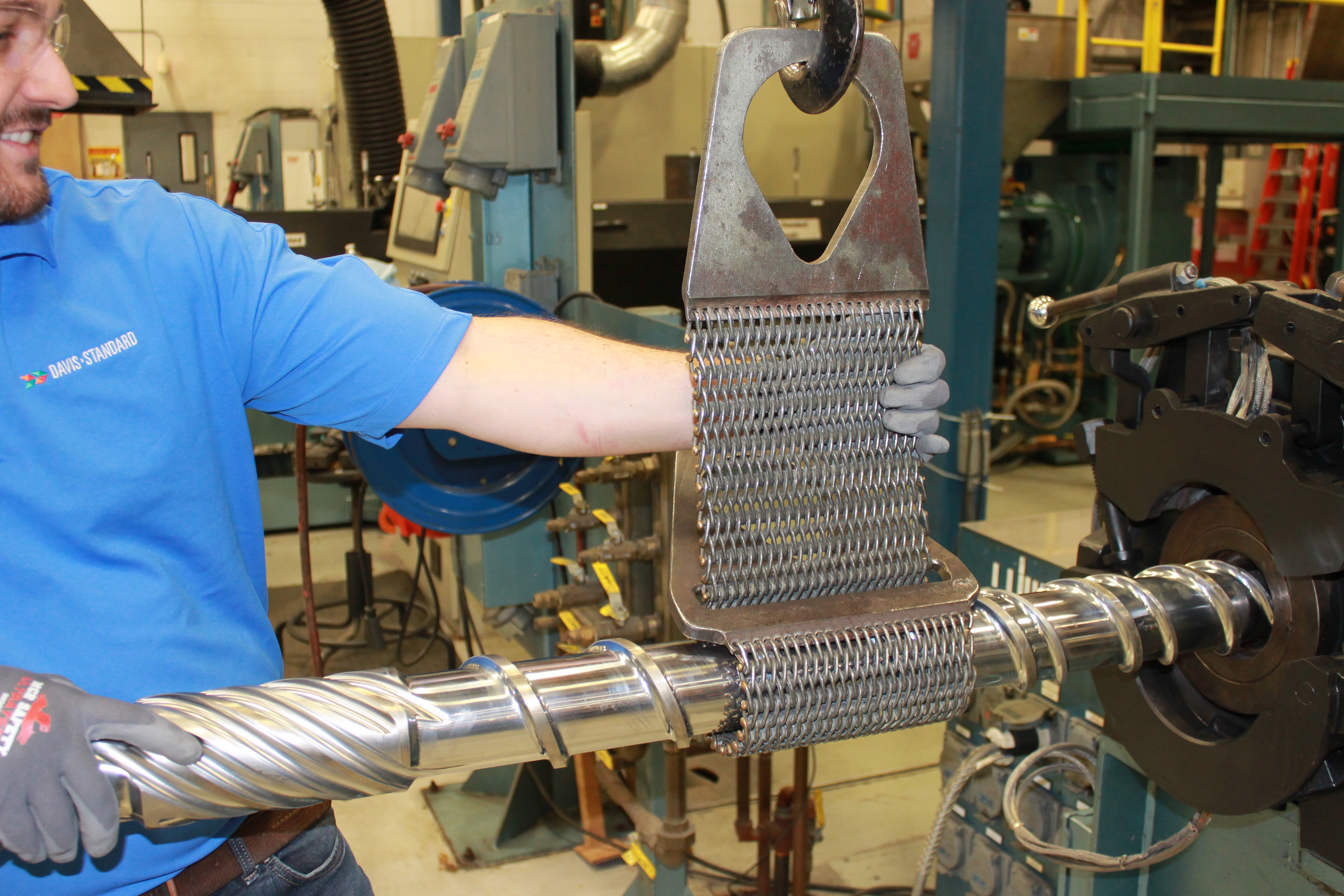
Achieving processing goals, product quality and avoiding unexpected equipment shutdowns are critical for operational excellence and profitability. Ensuring the feedscrew and barrel remain in top condition is an essential part of this equation. In part one of the Feedscrew and Barrel Maintenace, we will discuss feedscrew measurement.
Read More >
14-05-2019
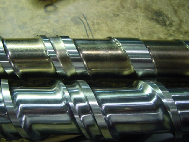
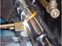
In part III of the Feedscrew and Design Truths for Improved Longevity series, we discuss how surface treatments or screw coatings can be used to improve screw wear.
Read More >
22-04-2019
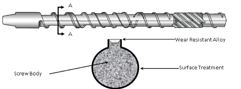
In Part II of the Feedscrew and Design Truths for Improved Longevity blog series, this blog will cover the importance of the feedscrew materials of construction.
Read More >
08-04-2019
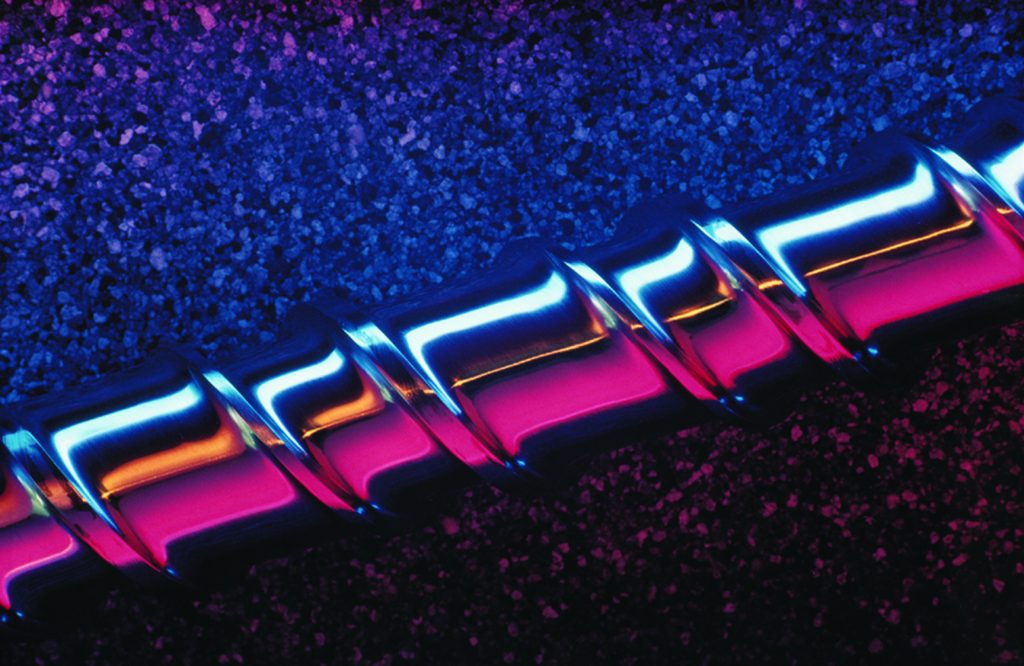
There are three types of feedscrew wear: abrasive, adhesive and corrosive. Depending on the polymers you process, these types of wear can be costly and frustrating. Read more about the causes and solutions we suggest at Davis-Standard.
Read More >
25-03-2019
You begin to notice motor speed issues, loud noises or see high-load readings for the drive. What’s going on and where do you begin? Our expert provides troubleshooting advice for your extruder, read here to learn more.
Read More >