
14-07-2020
As the fabric coating segment continues to evolve, processors should be prepared to take advantage of opportunities ahead. This blog covers key machine design considerations to ensure quality products and flexibility for growth.
Read More >
22-06-2020
In this blog, we highlight best practices to achieve strict cleanroom standards with regard to equipment construction, surface treatments and extruder design features.
Read More >
09-06-2020
Medical tubing applications continue to evolve while also playing a vital role in the delivery of quality healthcare worldwide. In this blog, we will cover some of the ways to plan ahead to achieve maximum ROI.
Read More >
26-05-2020
In this third blog post of our blown film series, Laura Martin, Director of Blown Film Technology at Brampton Engineering, discusses different blown film dies and selection considerations to ensure your blown film line has the die type best suited for your process.
Read More >
11-05-2020
In the last blog, we provided tips to help establish a baseline for application requirements and provided information on coater selection and coating formulations. In this blog, we’ll take that a step further by looking at the types of liquid coating substrates and characteristics, substrate surface tension/corona treatment guidelines and dryer selection.
Read More >
27-04-2020
The first step in building a world-class liquid coating line is properly defining the application. In this blog, we provide tips to help establish a baseline as well as information on coater selection and coating formulations.
Read More >
13-04-2020
To support Cast Film product consistency, limited waste and reduced downtime, we’ve put together a list of 10 common issues and how to troubleshoot them.
Read More >
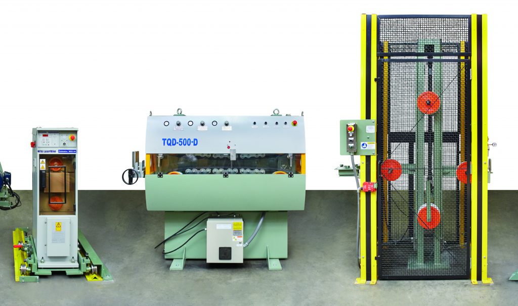
31-03-2020
The next in our Wire and Cable blog series, we cover the most significant reel handling components of a wire and cable line – takeups and payoffs.
Read More >
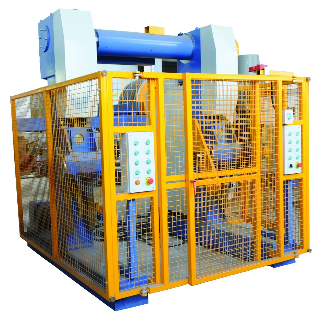
10-03-2020
Wire and cable systems involve many components. In this blog, we’ll focus on the component that ensures line speed stability – the capstan.
Read More >
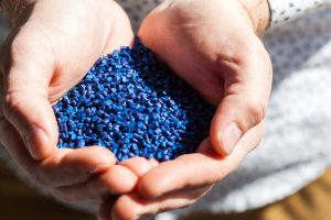
24-02-2020
Multilayer films require various resins to achieve specific properties in the final structure and also to improve processability during film production and converting. Learn about the basic characteristics of key resins used in blown film structures.
Read More >