

11-01-2021
let's kick the year off right! What better way than to start with maintenance. In this blog, we provide a checklist to ensure your extruder is primed for peak performance. Here are the 10 extruder components we suggest checking as part of a healthy maintenance plan.
Read More >

14-12-2020
In the final blog post of the year, we have recapped the top five most viewed posts of 2020.
Read More >
30-11-2020
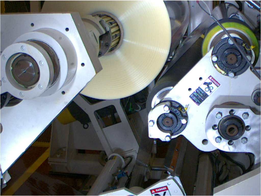
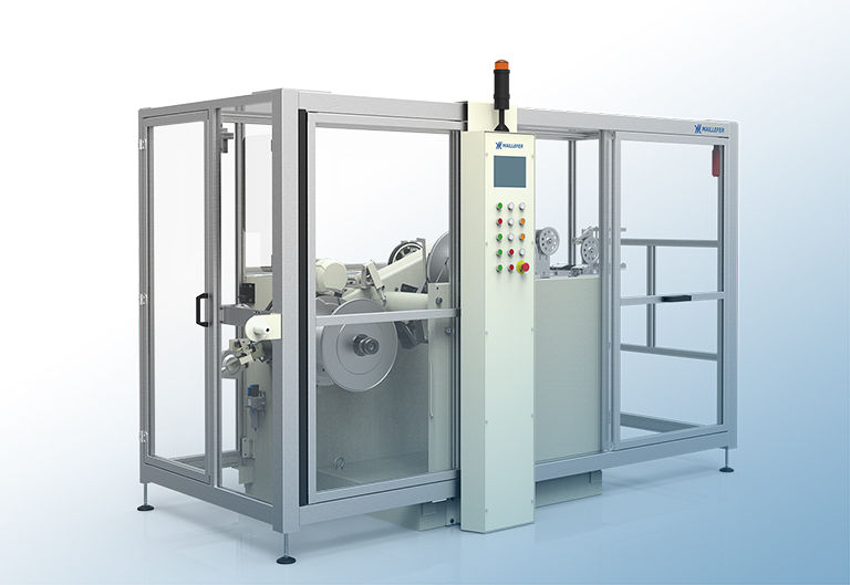
When it comes to substrate processing, consistent unwind splicing and winder transfers are paramount to quality and profitability. In this blog, we outline strategies for smarter splices and transfers.
Read More >
09-11-2020
keep your blown film operation running as efficiently as possible with these 10 troubleshooting tips.
Read More >
27-10-2020
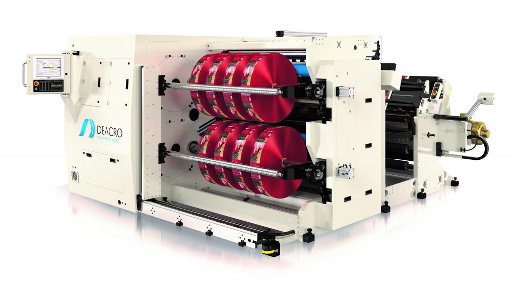
Automating your slitter rewinder process for flexible film production can yield significant advantages! In this blog, learn more about automation options that will help you capitalize on a market with an annual growth rate of 4.4 percent in an $85 to $95 billion end-use industry.
Read More >
12-10-2020
If you are considering the feasibility of bringing paint protection film (PPF) in-house, this blog provides a basic overview of PPF structures, required equipment and TPU resin options.
Read More >
15-09-2020
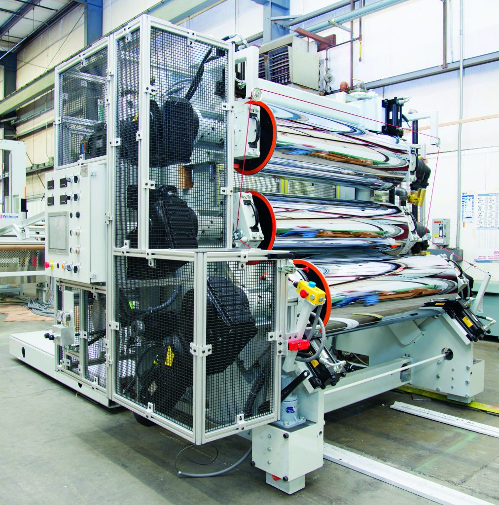
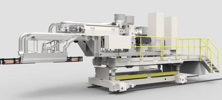
The new COVID-19 reality has placed PPE products front and center! PPE devices such as face shields are critical in protecting healthcare and other essential workers from viral airborne particulates. These shields, made from FDA approved clear plastic sheets, have not only proven their worth during the pandemic but are used in several other industrial and laboratory environments. Whether you’re already involved in the PPE marketplace or looking to expand, it’s important to evaluate sheet line capabilities. In this blog, we’ll take a look at primary machinery components and processing factors to consider. Extruder Requirements Whether using existing equipment or new equipment, the extruder needs to have sufficient torque to process the selected resin or possibly a speed increase for improved rate. For existing extruders: Evaluate motor horsepower and base gear in speed Understand available extruder torque versus required torque for resins to be processed Know the torque rating limit of the existing extruder gearbox; do not exceed the rating Belt drive extruder gearboxes can be modified by changing the sheave ratio to meet the desired torque and/or gear in speed increase A direct-coupled motor gearbox may require a gear ratio change For new equipment: Ensure capabilities are engineered for a range of resins Include extended field range motors Consider vented and plugged extruder barrels for greater flexibility Choose a flexible screw design for multiple materials as needed or optimized to fit your requirements Melt Pumps Since most sheet processes use a combination of regrind and virgin blends with variable bulk density, we recommend using a melt pump. Melt pumps reduce the output pressure variability to the downstream feedblock and die Improves machine direction thickness control Supports die performance for transverse thickness control (stable flow-thru die manifold) Offers melt stream bead stability in roll stand primary nip Operates around 700
Read More >
21-08-2020
Do you ever wonder what the advantages are switching from adhesive lamination to extrusion coating? In this blog, we’ll cover benefits and the factors that influence the switch to extrusion coating as well as typical product structures.
Read More >
10-08-2020
Next up in our blown film blog series, we discuss what to look for in an air ring to increase productivity and film quality.
Read More >
27-07-2020
Selecting the right coiling and reeling technology for your extrusion tubing application is essential. Here are a few tips to ensure the best possible outcome for coiling and reeling your extruded tubing.
Read More >