
14-06-2022
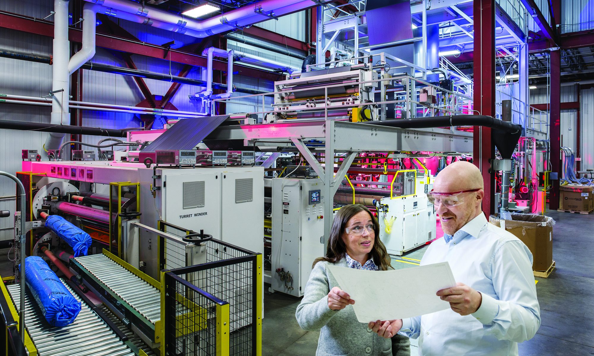
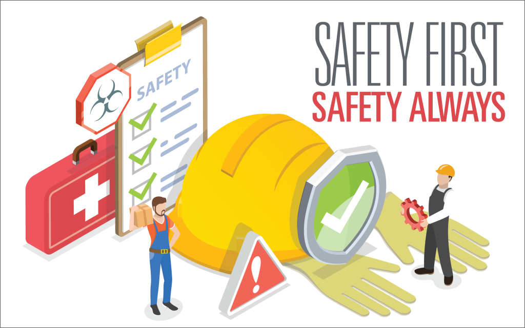
A healthy dose of safety training is a good way to prevent accidents while improving operational efficiency. Our EHS (Environmental, Health, and Safety) team has created the following tips to support a strategic approach to safety training.
Read More >
23-05-2022
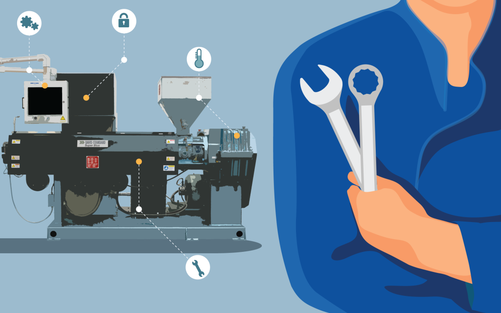
In this blog, we delve into maintenance by focusing on the extruder. Our team has put together their top 10 tips for keeping your extruder in top condition.
Read More >
10-05-2022
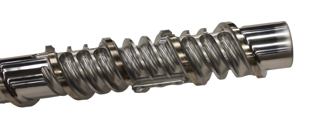
Expanding on the feedscrew longevity series we did back in 2019, this blog provides basic wear guidelines to assist you in knowing when to rebuild or replace your feedscrew
Read More >
26-04-2022
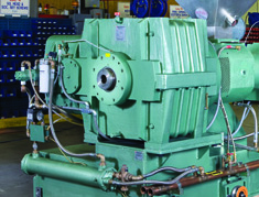
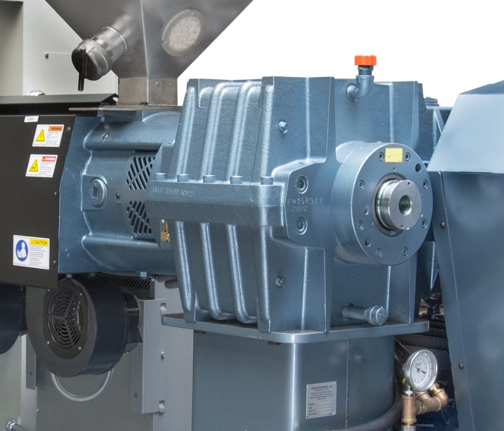
Selecting the right lubricant for your gear reducer is important to long-term operational success. In this final blog post of the series, we’ll provide guidance on oil selection.
Read More >
12-04-2022
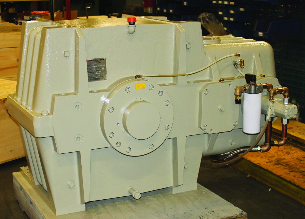
In the first blog of this series, we outlined oil change intervals. In this blog, we move on to the next step, flushing the gear reducer. Flushing is a clean-fluid circulation process that removes water, chemical contaminants, air, and particulate matter. Keep your gear reducer for the long-hall with these methods....
Read More >
29-03-2022
Oil changes! Do we need to say more to convince you how important this regular maintenance task is for your productivity and equipment longevity? Take a look at what we recommend for your gear reducers. Including reducers with and without filtration.
Read More >
14-03-2022
When it comes to the right surface coating for your blown film die, cost and performance can make or break your bottom line. Check out this blog where we review coating options for extrusion spiral dies beyond traditional chrome plating.
Read More >

23-02-2022
Do you know if your underwater pelletizer is providing you with the desired pellet quality and output? It is not uncommon for many to assume all is well, only to realize that die plate performance is not up to par. The good news is, checking is easy. Check out this blog to learn how you can maximize performance.
Read More >
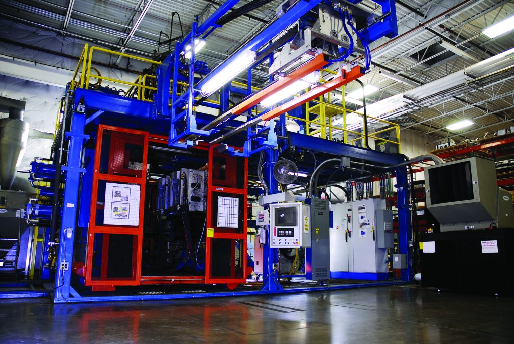
07-02-2022
Performance, prevention, and preparation are essential to ensure long-term efficiency and production from your blow molding equipment. Davis-Standard’s blow molding team put these 10 tips together to help you stay ahead of the curve, keeping your machinery performing its best!
Read More >
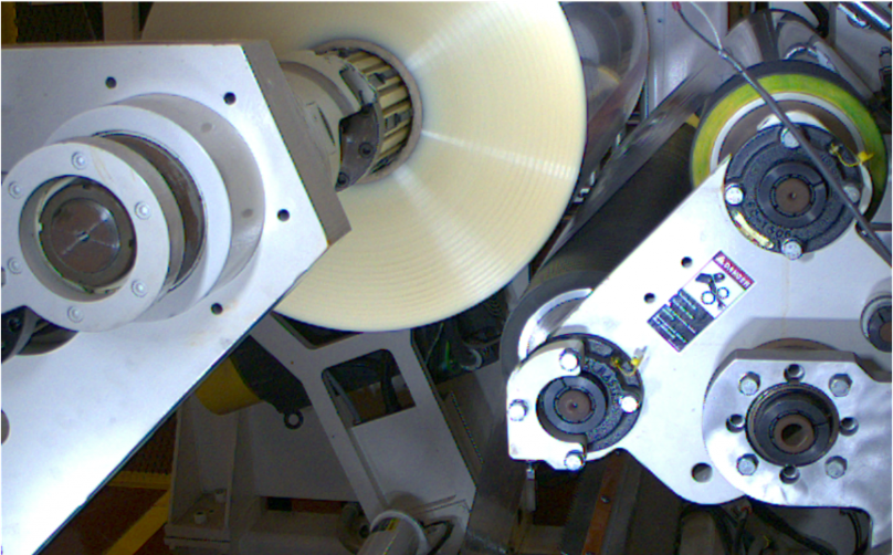
24-01-2022
Our industry has reached a point where scrap, downtime, and lost production due to missed splices during the unwinding and web transfer process should and can be prevented. Learn how in this blog...
Read More >