

13-12-2021
Last December we counted down our top five blog posts of the year. This was such a big hit, we’ve brought it back! Some of these blogs were written in 2020 and 2019, but they continue to capture your attention; landing in our 2021 count-down. Your readership and feedback is appreciated – thank you! Without further adieu...here are the top five most-read blogs of 2021. Coming in at number five is a popular post in our blown film series, which outlines factors for consideration when selecting the right air ring for your process. This includes an overview of air ring options based on the type of film and degree of desired flexibility, resins used, optimal outputs, and more. Check it out. https://davis-standard.com/custom_blog/what-to-look-for-in-an-air-ring-blown-film-series-part-iv/ At number four is our ever-popular blog about emergency feedscrew removal. Feedscrew removal can be daunting, but this blog helps alleviate your fears by summarizing 10 steps for safely removing your feedscrew. It also includes information on using a feedscrew jack to assist in this process. https://davis-standard.com/custom_blog/the-911-for-feedscrew-removal/ Taking the spot at number three, as part one of a series on maintaining your feedscrew and barrel, we cover the process of feedscrew measurement. Achieving the right clearance between the barrel and feedscrew is essential for attaining operational excellence while avoiding processing issues. Learn more about the bottom line impact of feedscrew and barrel maintenance. https://davis-standard.com/custom_blog/essential-feedscrew-and-barrel-maintenance-part-i/ In second place, many appreciate this step-by-step visual demonstration of purging flexible PVC from your extruder and die head. Valuable guidance on required tools, safety practices, equipment disassembly, and cleaning procedures is provided. https://davis-standard.com/custom_blog/purge-and-feedscrew-cleaning-video-tutorial/ Topping our list 🏆 for most views in 2021 is…drum roll please 🥁 …Troubleshooting Common
Read More >
29-11-2021
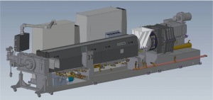
Smarter processing and a healthier bottom line depend on our ability to use available technology to our advantage! When it comes to HDPE product applications such as pipe extrusion, we have found that groove feed extruders offer significant advantages over smooth bore extruders. These benefits include increased output, reduced melt temperature, improved mixing quality, and linear consistency. In terms of environmental and economic benefits, you can enjoy a smaller footprint, reduced operating costs, and improved energy efficiency. All of these factors can add up quickly! So, what is it about a groove feed extruder that makes these gains possible, and what are the criteria you should consider before opting for this technology? First, let’s compare the operating principles of a smooth bore feed section versus a groove feed section. The frictional forces in an extruder exist between the barrel and solid bed to create forward conveying. A higher frictional force provides more efficient solids transport and vice versa. Due to the nature of groove feed design, frictional forces are higher, thus moving solids forward faster than a smooth bore extruder. This also enables higher processing rates with a lower melt temperature. We conducted two case studies to illustrate the advantages offered by a groove feed extruder when compared to a smooth bore extruder while processing high-viscosity HDPE materials. Both case studies compare a 3.5-inch (90mm) 42:1 L/D groove feed extruder versus a 4.5-inch (114mm) 30:1 L/D smooth bore extruder. The first case study compares grooved and smooth bore performance while processing a 0.2 MI (Melt Index) HDPE, and the second uses an 8 HLMI, ( High Load Melt Index), bi-modal HDPE. Both case studies compare the performance of the extruders at 1100 pounds per hour. The performance data summarized in the charts highlight the advantages of using a high-performance
Read More >
09-11-2021
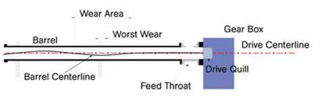
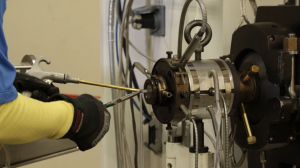
Is alignment important in order to optimize your extruder investment? You bet it is! And the longer the extruder barrel, the more significant alignment becomes. A poorly aligned extruder causes excessive wear and tear on both the screw and barrel. We’ve seen misalignment cause costly and unnecessary damage including premature wear, bent and broken screws, unstable barrels, heater crawl, thermocouple shearing, additional drive load, and die movement. In this blog, we’ll discuss the value of extruder alignment and why using a barrel support system is important to protect your investment. We have also included a boroscoping video at the end. First, the barrel must be aligned to the driving mechanism, which is the drive quill of the gearbox. No exceptions. Trying to determine alignment by leveling is inaccurate as it is not indicative of the drive quill and only measures the vertical plane. The correct procedure involves using an optical or laser alignment scope inside the drive quill to align the barrel to a fixed center line by rotating the drive quill. The barrel and feed throat are then aligned to that center line by adjusting the barrel supports, or the mounting faces of the feed throat. There are a number of quality support system designs available, but take note of the following considerations during selection. First, the barrel must be able to freely expand through the support(s) as it is heated without distortion. The barrel should never be locked down by a support that completely surrounds it. This prevents the barrel from having the necessary room to slide when expanding. Secondly, the support joints need to be made from non-corrosive materials, such as brass, which will prevent “freezing” of the support. Finally, the entire barrel support must be rigid enough to maintain its position rather than tipping over as
Read More >

25-10-2021
Creating a culture that values safety in the workplace is a key driver of quality, performance, and profitability. This blog will discuss the value of implementing a safety program.
Read More >

12-10-2021
In the third part of the digital transformation series, we will take you through the three aspects of information processing - perception, understanding/interpretation, and prediction. By adopting situational awareness through technology, you will be able to enhance your extruder's performance and profitability.
Read More >

27-09-2021
In this second blog of our digital transformation series, we explain the digital architecture of a cloud-based system using DS Activ-Check™ as an example and review its advantages.
Read More >

13-09-2021
In the first part of this exciting Digital Transformation 3-part series, we'll discuss what digital transformation is and how it has evolved and has affected our industry today and in the future. This is one series you certainly do not want to miss!
Read More >
24-08-2021
Purging flexible PVC from your Davis-Standard extruder and die head after each use is essential to maintain optimal equipment operation. This video tutorial includes the required tools, safety practices, equipment disassembly, and cleaning procedures for removing excess PVC from your flange, die head, mandrel, and feedscrew.
Read More >
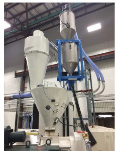
09-08-2021
In the second part of the reclaim series, we take a step further by delving into the benefits of feed-assisted single screw extruders, including a crammer feeder, ram stuffer, and cutter compactor. Feed-assisted single screw options are a game-changer when bulk density is too low for gravity feeding or when dealing with problematic feeding material.
Read More >
13-07-2021
Reclaim extrusion is a worthwhile pursuit for processors looking to achieve sustainable practices while taking advantage of cost savings from re-using available materials. In the first part of this blog series, we’ll cover the basic characteristics of low bulk density materials as well as various single screw extruder designs.
Read More >