
11-02-2020
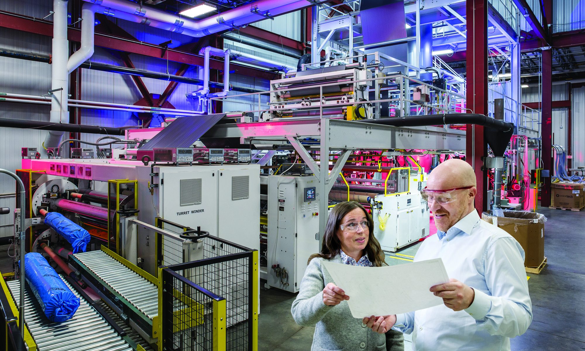
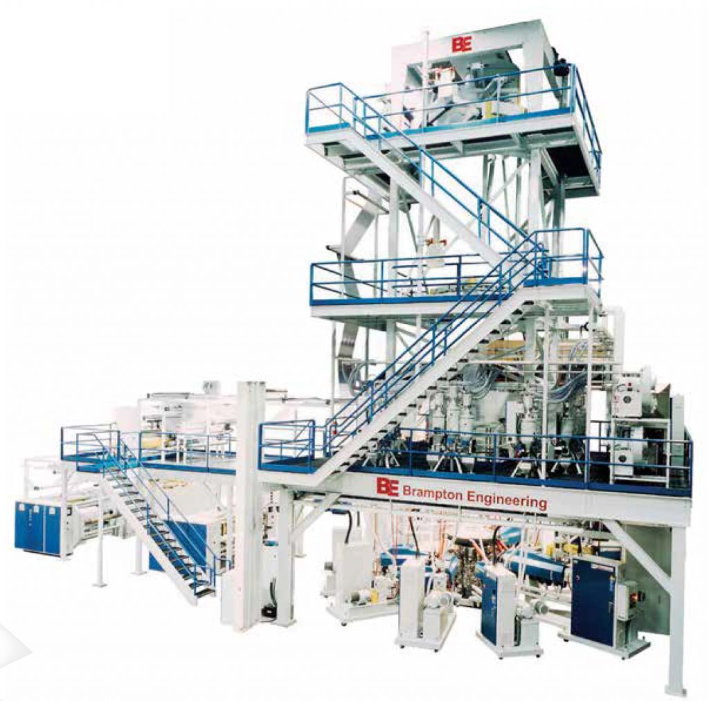
In the first of the blown film series, we’ll highlight some common film applications and the associated equipment that goes along with them.
Read More >
27-01-2020
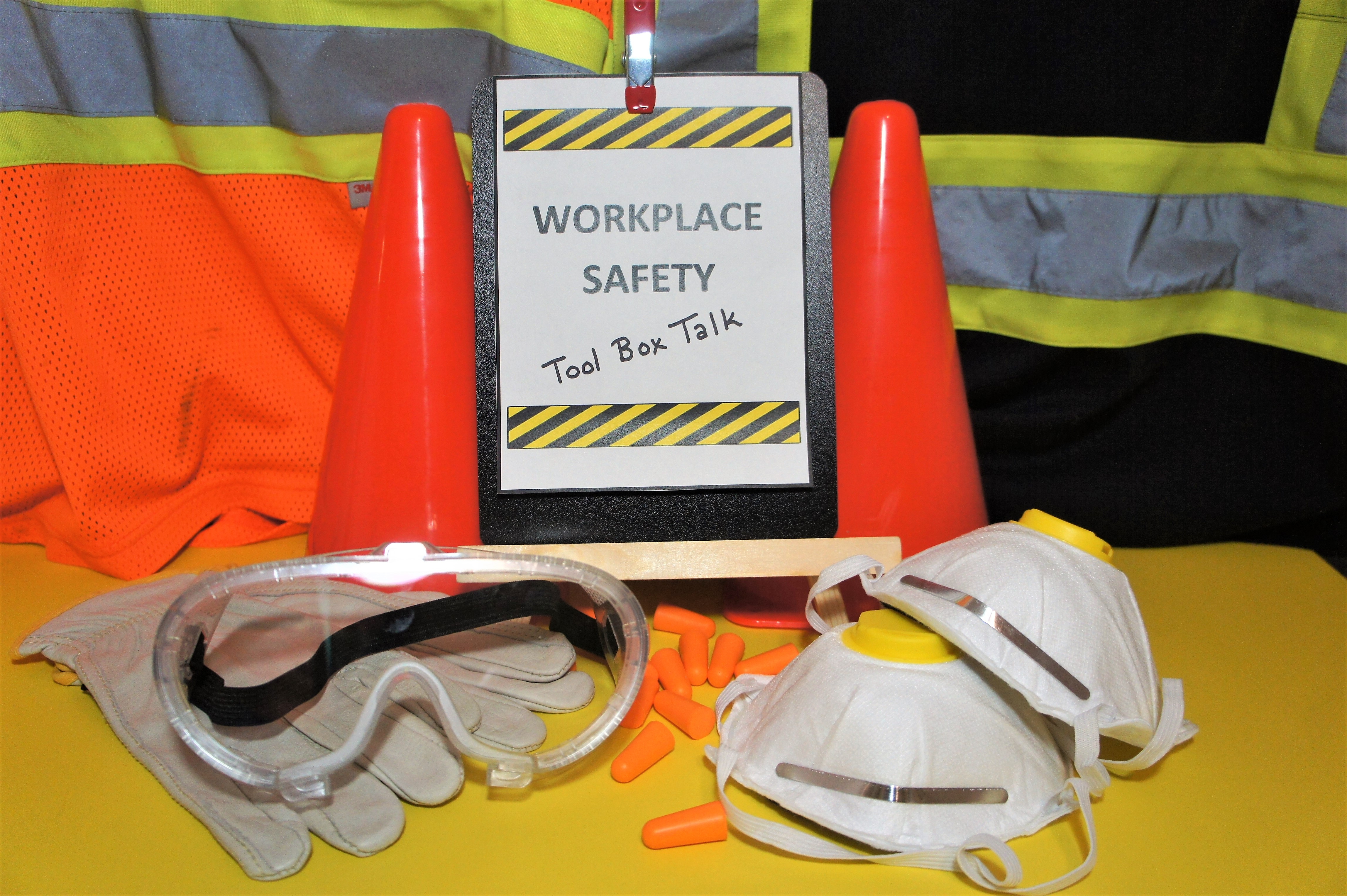
Good safety practices are essential in keeping employees injury-free on the job, reducing downtime, and maximizing daily productivity and efficiency. Here are our top 10 tips for safe processing.
Read More >
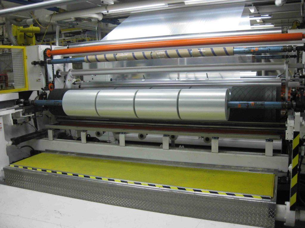
10-12-2019
Take advantage of the pros of in-line slitting with the 5th blog of our winding series!
Read More >
26-11-2019
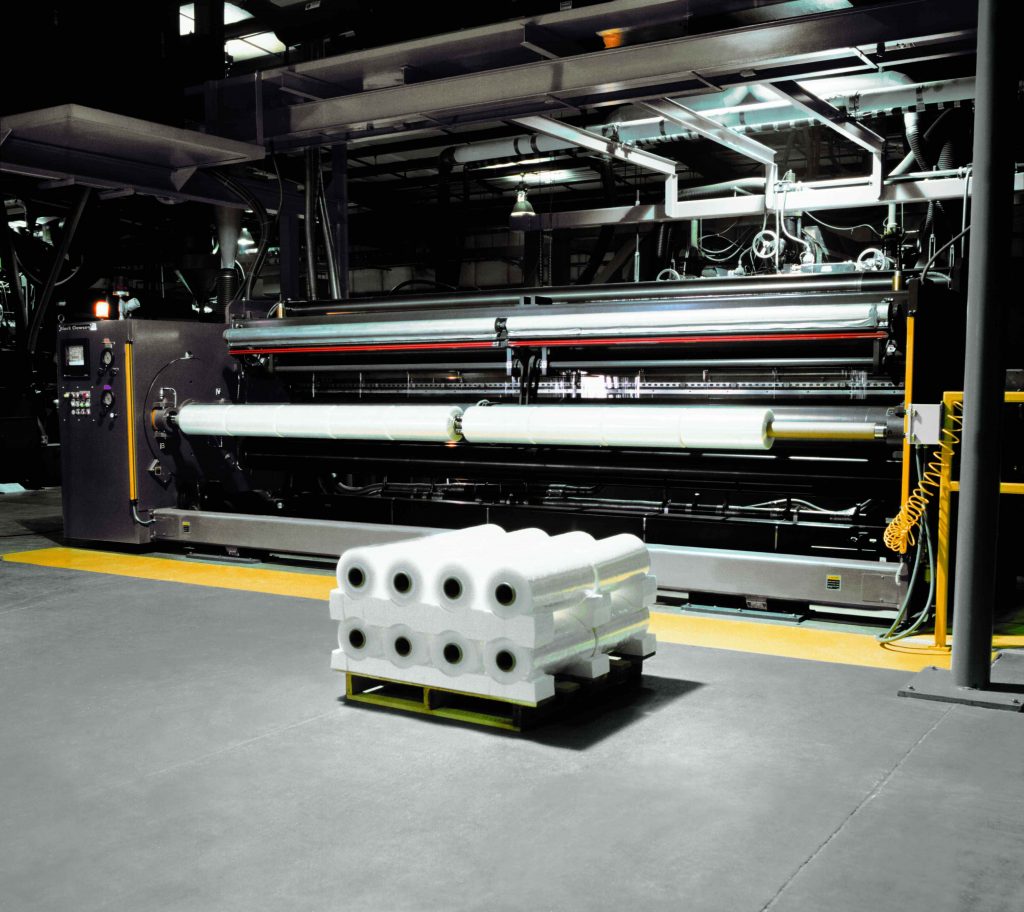
In this blog, we’ll discuss the advantages and disadvantages of the three basic winding processes used for winding web materials. These are center winding, surface winding and a combination of center-surface winding.
Read More >
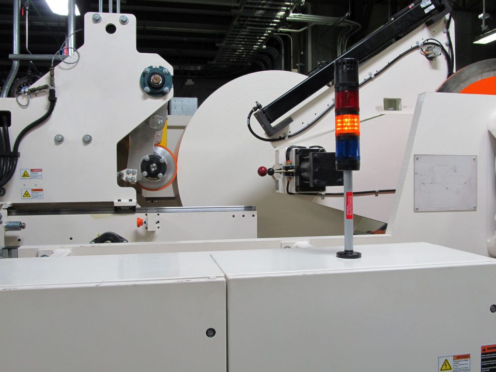
11-11-2019
The ability to wind good rolls on a consistent basis is a challenge for every winder operator. It is truly an art! This blog covers the importance of roll density and application of “TNT” principles in winding good rolls.
Read More >
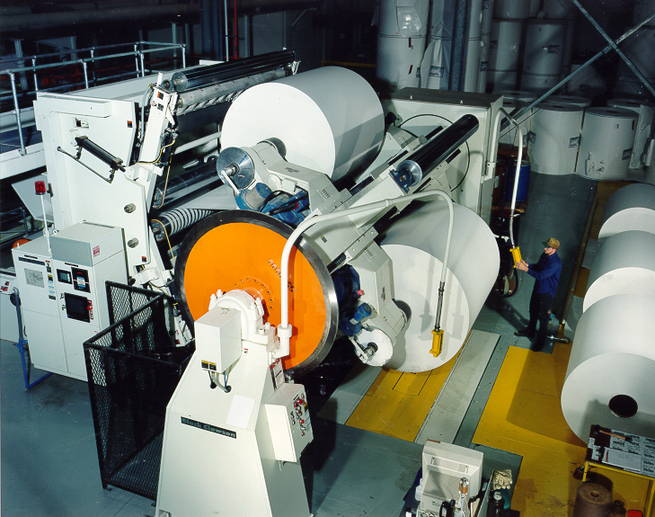
28-10-2019
To meet today’s productivity requirements for continuous unwinding and splicing operations, it is important to understand the components of a splicer operation. Optimizing each component is critical to improving splicing efficiency and total productivity.
Read More >
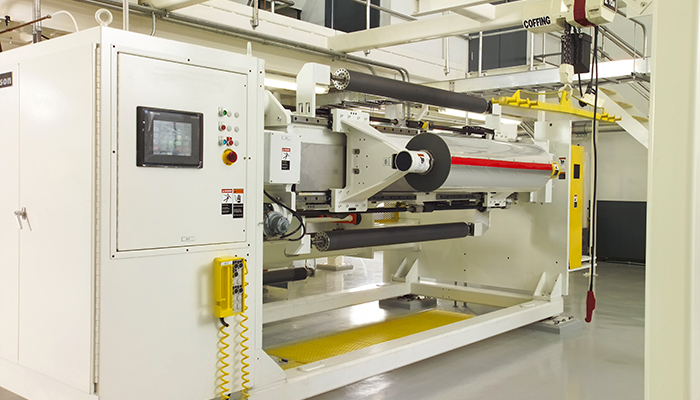
16-10-2019
In the first Winding series, we offer 5 tips to simplify the winding process, boost profitability and ship quality rolls. Ultimately it all begins with technology!
Read More >

25-09-2019
The K Fair is a gold mine when it comes to networking and educational opportunities. Here are our top resources for connecting with peers and gaining industry knowledge.
Read More >

09-09-2019
As with any trade show, but especially with K, you must plan, plan, plan. Our K show experts have compiled a list of 10 resources to help you maximize your time and eliminate unnecessary headaches.
Read More >
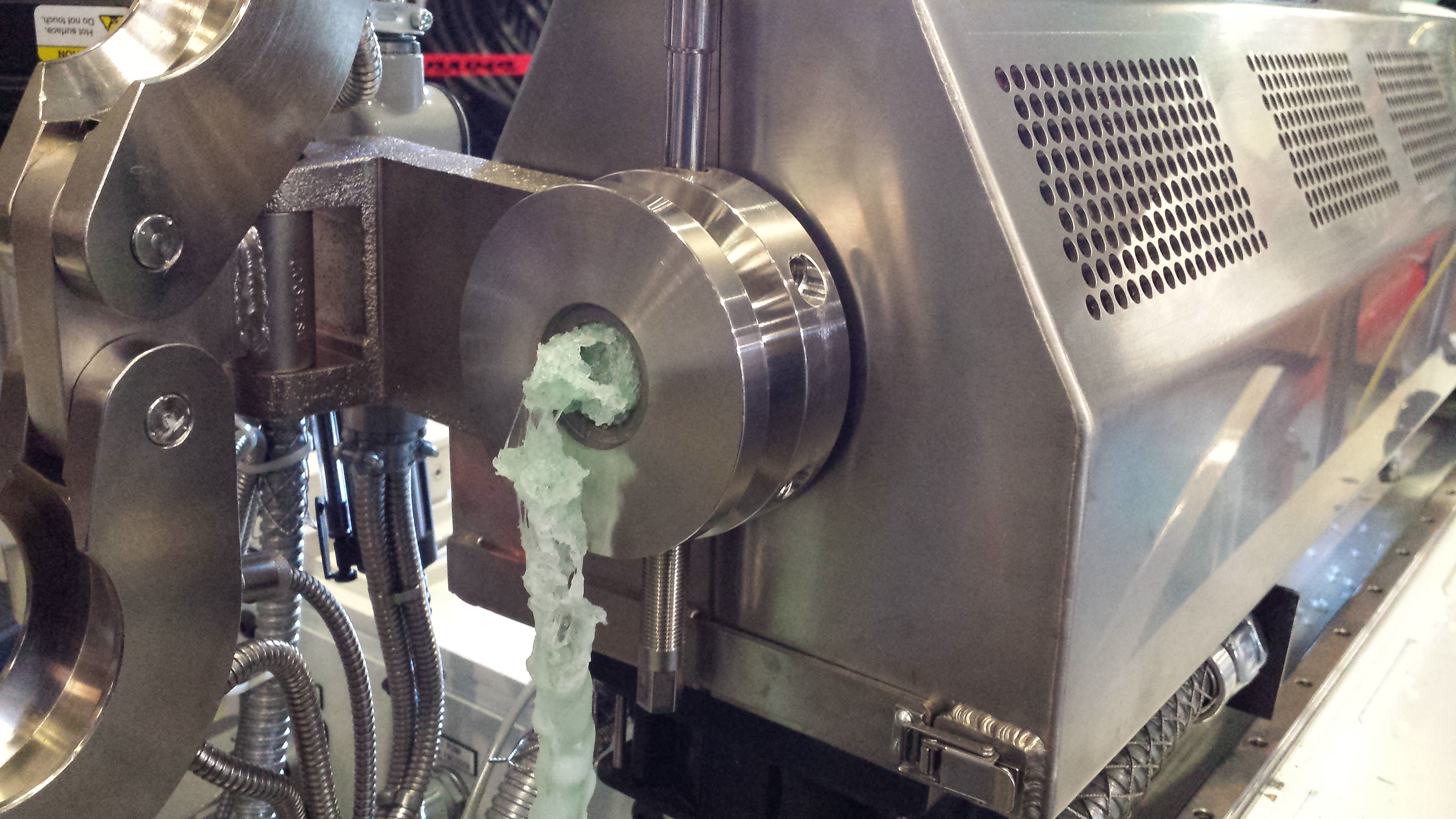
26-08-2019
In this blog, we will focus on a two-step purging process. This includes a high-viscosity resin purge followed by a cast acrylic purge.
Read More >