Previously in this blog series, we’ve analyzed a variety of applications for multi-layer blown films, the different resins used in blown films, and the co-extrusion dies used to integrate the resins into multi-layer structures. The next consideration is the air ring used to cool and control the film bubble as it inflates, which is key to high productivity and film quality.
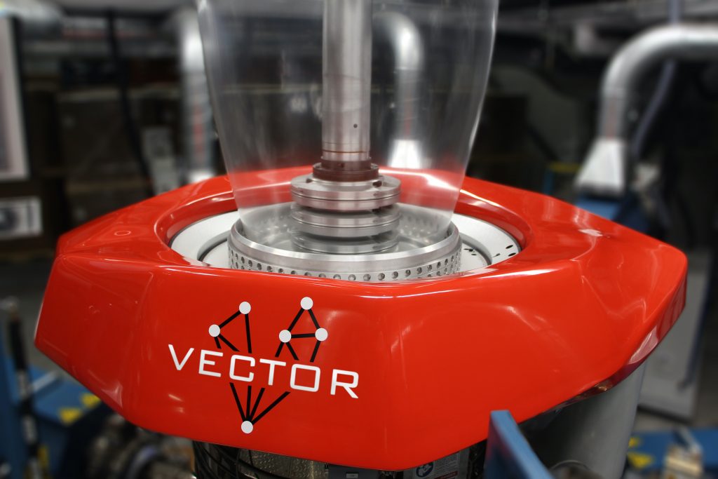
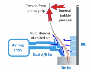
The cooling system consists of a blower, chiller, ducting, and air ring entry (which may require a manifold) to distribute the chilled air around the die exit, and an annular lip to direct the air onto the film bubble for cooling and bubble stability. It’s important the blower and chiller provide sufficient cool air for optimal air ring performance. The ducting between the remote air supply and the air ring can also impact performance dramatically if it is too long, takes too many bends, or is uninsulated. Measuring the temperature and flow rate of chilled air at the inlet to the air ring is always wise.
Internal bubble cooling (using an IBC device) similarly directs chilled air to the inside surface of the bubble and also exhausts warmer air to maintain the bubble size. Adding an IBC could increase output by 20 percent or more, as long as cooling is the only limitation. An IBC system also requires chilled air capacity, plus two more blowers for inlet and exhaust streams, as well as some type of bubble diameter sensing and control device.
The most effective air ring design depends on the type of film and the degree of flexibility required. If a blown film line is primarily producing one type of polyolefin film with a structure designed to run fast and stable (i.e. blends of resin grades that form a very stable bubble), then elevated air rings and triple lip air rings permit these film structures to run at very high outputs. However, these air rings are not as easily adjustable for large BUR ranges or other films that behave differently, such as a barrier film with heavy, low-melt strength PA and EVOH.
A dual lip air ring is often a good compromise for fairly high output rates while also offering flexibility to run different types of films. Flexibility comes from the following features:
1) The ability to adjust the fraction of air directed to the hottest resin exiting the die lip via the lower lip
2) A suitable expansion angle leading to the upper lip, and
3) Control over the angle and expansion of the main flow of air from the upper lip, enabling adjustment of the low-pressure region that results in “bubble lock.”

High cooling rates and a good bubble lock need to be consistent around the bubble circumference for optimal productivity and film quality. The air ring entry distributes the chilled air coming through the duct around the perimeter. Many air rings do this by splitting the air supply with a manifold into four to eight equal-length ducts to supply multiple inlets spaced around the entry. The entry then further spreads out the airflow with aerodynamic contouring or baffles, which can increase the pressure losses and reduce the maximum airflow rate. This leads to lower outputs as well as greater energy consumption. Single inlet entries can reduce pressure losses by eliminating the manifold, but airflow uniformity around the circumference becomes more challenging. A well-designed single inlet entry can increase the cooling capacity of a chiller-blower system dramatically.
Most air rings also have additional features above the air orifices to help stabilize and support the bubble. Some can also improve cooling by continuing to direct the chilled air closer to the bubble surface. These additional supports must be appropriate for the size and shape of the bubble, which varies based on the film structures (resins) and the width of the film. Other types of air rings have been designed for specific applications, such as heavy-duty shipping sacks and HDPE, which has a high-stalk shape of a bubble .
Have questions or wish to comment on this blog post? Write to us below!
We are happy to discuss your air ring needs and find the technology best suited for your film process. Please contact marketing for inquiries or visit Brampton Engineering to learn more.
Do not hesitate to contact our service team if you need emergency assistance (844 MYDAVIS).
Stay safe and healthy!
Cheers,
The D-S Connect Blog Team

Please quote for a blown film line for Fep material to make blown sizes starting from
2 inches to 8 inches blown size .We want to make Fep heat shrink tubes in coils and folded
Condition and to shrink ratio 1.1.3: 1 for use as tube light covers and rollers for Zerox and printers.
We wonder if these can be made with higher shrink ratios 2:1 and sizes from 1 mm onwards to 6 mm( these sizes are in mm and not inches)
Hi Prakash: Thank you kindly for your inquiry. we are sending your request to the blown film team now. Someone will be in touch asap.